








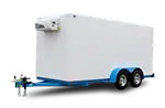


Four cars, two deck levels, and one opportunity to get the load right before you enter highway traffic. A 4-car wedge hauler may look straightforward, but its usable positions, deck geometry, axle placement, hitch load, and clearance limits all affect how the vehicles must be arranged. Put too much weight forward and the tow vehicle can exceed its rear-axle, tire, suspension, or hitch rating. Put too little weight on the hitch and the trailer can become unstable. Poor loading can contribute to sway, reduced steering or braking control, component failure, and loss of control.
Here’s how to load a 4-car wedge trailer properly, starting with the trailer’s certified ratings and manufacturer loading instructions and ending with every vehicle secured and rechecked correctly.
Know Your Trailer Before You Load Anything
There is no universal set of dimensions or weight ratings for every 4-car wedge trailer. Commercial multi-vehicle carriers may use gooseneck, fifth-wheel, or semitrailer configurations, and their deck lengths, axle arrangements, empty weights, GVWRs, and usable vehicle positions vary considerably. Some are designed for pickup-based hotshot combinations, while larger carriers require an appropriately rated medium-duty truck or truck tractor. Do not assume that a trailer can legally carry four vehicles merely because four will physically fit.
A 4-car carrier may have tandem or tridem axles, but the number of axles does not establish its legal payload. Each axle has a gross axle weight rating, and the complete trailer has a certified GVWR that may be lower than the sum of the axle ratings plus the expected hitch load. Tires, wheels, suspension, brakes, coupler, frame, deck, and hitch components impose additional limits. Available cargo capacity is the trailer’s certified GVWR minus its actual empty weight and any equipment carried on it, not an estimate based only on axle ratings.
Before a single car rolls on, check at least these three numbers:
- Trailer GVWR (shown on the trailer’s federal certification/VIN label)
- GAWR and tire ratings (shown on the certification label and tire sidewalls; axle identification labels may provide additional component information)
- Tow vehicle GCWR and individual ratings (consult the truck’s certification label, owner’s manual, towing guide, and any body-builder or upfitter information)
Also record the tow vehicle’s GVWR, front and rear GAWRs, tire and wheel capacities, receiver or gooseneck rating, and maximum allowable trailer weight. Use the actual scale weight of each vehicle whenever possible. Two full-size pickups can easily weigh 11,000 lbs or more together, but a trailer’s advertised empty weight is not its loaded weight. Drivers, passengers, fuel, tools, chains, straps, spare tires, winches, and other cargo all consume the truck’s or trailer’s available capacity. The combination must remain within every applicable rating, including the truck’s GCWR and axle ratings, not merely within a headline tow-rating figure.
Upper Deck vs. Lower Deck: What Goes Where
The wedge design places some vehicles higher and often farther forward than others. That geometry affects the trailer’s center of gravity, hitch load, axle-group load, overall height, and clearance between vehicles and decks. Moving a vehicle only a short distance can transfer hundreds of pounds between the hitch and trailer axle group, especially when the vehicle is far from the axle centerline.
Heavier vehicles should not automatically be assigned to a particular deck without considering the carrier manufacturer’s loading diagram. A heavy vehicle placed far forward can overload the truck’s rear axle, hitch, tires, or suspension. The same vehicle placed too far behind the trailer axles can remove necessary hitch weight and increase instability. Higher positions also raise the combination’s center of gravity. Use the trailer manufacturer’s approved vehicle positions, then confirm the completed arrangement on a scale.
Lower positions near the trailer axle group are often useful for heavier or lower-clearance vehicles, but deck capacity and axle loading still control. Each platform, ramp, hydraulic mechanism, support, and loading position may have its own capacity. Never infer a position’s capacity solely from where it sits in relation to the axles, and never exceed a deck or ramp rating even when the trailer remains below its overall GVWR.
Load Order: A Step-by-Step Sequence
Loading order depends on the carrier’s movable decks, ramps, hydraulic controls, wheel pockets, tie-down access, and approved loading diagram. The following sequence is a safe planning framework, but the trailer manufacturer’s instructions take priority.
- Plan the complete load before moving the first vehicle. Record each vehicle’s actual weight, wheelbase, length, width, ground clearance, and height. Assign all four positions while accounting for trailer GVWR, deck and ramp capacities, axle loads, hitch load, overall height, and adequate space to operate every tie-down.
- Load positions that will become inaccessible first. On many carriers, this means loading a forward or elevated position before a vehicle blocks its ramp, deck controls, or tie-down anchors. Engage the parking brake, place the transmission in the position specified by the vehicle manufacturer, and secure that vehicle before changing a movable deck.
- Load the remaining forward or lower position. Maintain the planned spacing between vehicles and preserve access to all approved anchor points. Do not rely on a wheel stop alone to hold a vehicle during loading or deck movement.
- Load the final rear position only after checking the developing balance. Confirm that the trailer remains stable, all decks and supports are fully locked, and no secured vehicle can contact another vehicle, the trailer structure, or the tow vehicle during normal suspension movement.
Vehicles generally occupy individual positions along the trailer’s length rather than sitting side by side. Federal width limits commonly restrict commercial vehicles to 102 inches on the National Network, excluding only qualifying safety devices, but the trailer’s certified width and the rules for the intended route still control. Balance the load through approved fore-and-aft placement, not by deliberately positioning a vehicle off-center. Keep each vehicle centered in its designated wheel channels unless the manufacturer provides different instructions.
Weight Balance: The Numbers Behind the Feel
Use the trailer manufacturer’s specified hitch-weight range. Conventional bumper-pull trailers commonly require roughly 10% to 15% of loaded trailer weight on the hitch, while many gooseneck and fifth-wheel trailers are designed around a higher percentage, often approximately 15% to 25%. These are planning ranges, not permission to exceed the tow vehicle’s payload, GVWR, rear GAWR, tire ratings, hitch rating, or the trailer’s coupler rating. The correct result is the manufacturer’s specified percentage while remaining within every individual component rating.
Weigh the complete loaded combination at a certified public scale before beginning the trip. Obtain separate readings for the tow vehicle’s steer axle, drive or rear axle, and the trailer axle group. A reweigh with the trailer disconnected may be needed to calculate actual trailer weight and hitch load accurately. Scale fees vary by location and operator, so confirm the current charge at the facility. A total-weight ticket alone is insufficient: a combination can be below GCWR and trailer GVWR while still exceeding a truck axle, trailer axle group, tire, wheel, hitch, deck, or bridge-formula limit.
Do not depend on an assumed empty center of gravity or a catalog payload figure. Trailer options, spare tires, winches, ramps, toolboxes, fuel, and repairs can change empty weight and balance. Use the trailer’s certification label and current manufacturer instructions, obtain actual empty and loaded scale weights, and keep the tickets with the vehicle records. Reweigh whenever the mix or placement of vehicles changes materially.
Deck Level Differences and Clearance
The height and slope of an upper deck vary by carrier, and guessing can produce an overheight combination or serious vehicle damage. Measure from the pavement to the highest point of every loaded vehicle after the suspension settles and the decks are locked in their transport positions. Include roof racks, antennas, light bars, spoilers, exhaust stacks, and any other projecting equipment. Indiana’s general maximum vehicle height is 13 feet 6 inches unless a route, structure, permit, or vehicle classification imposes a different restriction. Route clearance must be verified rather than assumed from the legal maximum.
Low-clearance cars can scrape at the ramp toe, ramp-to-deck transition, breakover point, or movable-deck hinge. Measure front and rear overhang, approach angle, departure angle, breakover angle, and the lowest components, including splitters, exhaust parts, battery trays, rocker panels, and suspension hardware. Use purpose-built, load-rated approach extensions or race ramps when the trailer manufacturer permits them. Secure portable ramps against movement, keep personnel clear, and never improvise with loose lumber of unknown strength.
A lower position may provide a gentler loading path and keep a tall vehicle from exceeding the legal height, but that is not guaranteed on every carrier. Confirm ramp angle, deck transition, deck capacity, loaded height, tie-down access, and weight distribution for the specific trailer. When a vehicle cannot be driven safely, use a properly rated winch and approved attachment procedure rather than spinning the tires, building momentum, or standing in the winch line.
Securing Each Car: Tie-Down Points and Strap Specs
For commercial interstate transportation, automobiles, light trucks, and vans that individually weigh 10,000 lbs or less are covered by 49 CFR 393.128. Each vehicle must be restrained at both the front and rear by at least two tie-downs, with the tie-downs attached to the vehicle’s mounting points and to the trailer’s anchor points. Wheel nets, over-the-tire straps, axle straps, or manufacturer-approved vehicle tie-down points may be appropriate depending on the carrier and vehicle. Never route a strap through a wheel opening, around a sharp edge, or over a brake hose, wiring harness, steering component, body panel, or other part not approved for securement.
Use a minimum of four properly arranged tie-downs per vehicle: two providing front restraint and two providing rear restraint. The general securement rules also require the aggregate working load limit of the securement system to be at least one-half the cargo’s weight, but meeting that number alone does not satisfy the automobile-specific front-and-rear securement requirements. A vehicle over 10,000 lbs is subject to the heavy-vehicle requirements of 49 CFR 393.130, including at least four tie-downs attached as close as practicable to the vehicle’s front and rear.
Select tie-downs by their labeled working load limit, intended application, hook and anchor compatibility, length, and condition rather than webbing width alone. A 2-inch strap does not automatically have a 3,333-lb WLL, and a wider strap is not automatically appropriate for a tire or wheel. The WLL of a securement assembly is limited by its lowest-rated component, including the strap, chain, hook, fitting, ratchet, track, and trailer anchor. Do not use breaking strength as working load limit.
| Vehicle Weight | Minimum Arrangement | Federal WLL Baseline | Securement Selection |
|---|---|---|---|
| Under 3,000 lbs | 2 front and 2 rear tie-downs | Aggregate WLL of at least 50% of vehicle weight | Labeled automotive wheel restraints or approved vehicle-point assemblies compatible with the trailer |
| 3,000 to 5,000 lbs | 2 front and 2 rear tie-downs | Aggregate WLL of at least 50% of vehicle weight | Four independently inspected, properly rated automotive tie-down assemblies |
| 5,000 to 7,500 lbs | 2 front and 2 rear tie-downs | Aggregate WLL of at least 50% of vehicle weight | Higher-capacity assemblies where required by the vehicle, anchors, angles, and carrier instructions |
| Over 7,500 to 10,000 lbs | 2 front and 2 rear tie-downs | Aggregate WLL of at least 50% of vehicle weight | Verify every mounting point, anchor, fitting, and assembly against the actual vehicle weight |
Tension each restraint according to the strap, carrier, and vehicle manufacturers’ instructions. Over-the-tire systems are intended to restrain the tire while allowing normal vehicle suspension movement; frame or axle securement may compress the suspension and requires a different procedure. Do not judge proper tension by how little the body rocks, and do not overtighten straps until tires, wheels, suspension, bodywork, tracks, or anchor points are damaged. Protect webbing from abrasion and heat, close and lock ratchets fully, secure loose strap tails, and remove from service any assembly with cuts, melted fibers, damaged stitching, bent hardware, illegible WLL markings, excessive wear, or unauthorized repairs.
One Check Before You Move
Walk the full load after securing it. Check all four restraints on every vehicle, verify that hooks and fittings are fully seated, close each ratchet, secure excess webbing, and confirm that no strap is twisted across a tire or bearing against a sharp edge. Verify parking brakes and transmission settings as directed by the vehicle and carrier manufacturers. Confirm that movable decks, ramps, hydraulic cylinders, safety props, pins, latches, and transport locks are fully secured. Check the coupler, safety chains where applicable, breakaway system, electrical connector, lights, tires, wheel fasteners, and license plate visibility.
Move slowly to a safe inspection area, stop, and recheck the entire load. Commercial drivers must also comply with the cargo-inspection requirements in 49 CFR 392.9, including inspecting the load and securement devices within the first 50 miles and making adjustments when necessary, then reexamining them when duty status changes, after three hours or 150 miles of driving, and whenever required by the regulation. Stop sooner after rough pavement, hard braking, or any sign that a vehicle or tie-down has shifted.
If you’re shopping for a car hauler or need to look at what’s currently available, browse our full inventory or call us at (812) 829-0226. We stock Diamond C and H&H car haulers and can help match the trailer, tow vehicle, hitch, payload, deck length, axle configuration, and ramp system to the vehicles you expect to transport. Diamond C’s current car-hauler lineup consists of single-vehicle flat-deck trailers rather than a purpose-built 4-car wedge carrier, so verify the exact manufacturer, model, certification label, and approved loading plan when shopping for a multi-vehicle commercial transporter.
What’s the heaviest single vehicle you expect to transport, and what are the actual weights of all four vehicles together? Those numbers, combined with the tow vehicle’s ratings and the trailer’s certified capacity, determine what size and configuration you actually need.


