










Nothing kills a trip faster than taillights that work in the driveway and go dead the moment you hit the highway. You check the plug, wiggle the connector, and everything comes back on. You pull out anyway. Fifty miles later, another driver flashes you because your running lights have disappeared again.
That is often a hidden wiring problem. On many trailers, the wiring is the last system anyone inspects until a light, brake, breakaway circuit, or auxiliary function stops working. By then, moisture, corrosion, vibration, or abrasion may have been developing out of sight for months.
Here is how to find those problems before they find you on the road.
Why Trailer Wiring Corrodes So Fast
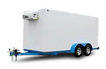
Trailer wiring operates in one of the harshest environments for an electrical system. It rides close to the pavement, gets sprayed with water, road salt, mud, and deicing chemicals, runs near moving suspension components, and often sits outdoors between uses. On a typical enclosed cargo trailer, portions of the harness may run along or inside the floor structure, with exposed branches near the axles, brakes, marker lights, and rear lamps. On a flatbed or equipment trailer, more of the wiring may be visible beneath the deck, but visible does not necessarily mean easy to inspect.
Copper conductors, terminals, steel frames, aluminum structures, and plated connector parts can all be affected by moisture and road chemicals. Where dissimilar metals meet, moisture can accelerate galvanic corrosion. Poorly sealed splices can also draw water beneath the insulation through capillary action. The outside of a connector may look acceptable while the conductor inside has turned green or black and become brittle.
Quality trailers may use jacketed harnesses, sealed connectors, junction boxes, grommets, and protected routing to reduce exposure. That is a strong starting point, but no wiring system is maintenance-free. A damaged connector seal, loose cable clamp, crushed section of loom, incorrectly installed accessory, or stone impact can create an entry point at any age. Inspection frequency should be based on mileage, storage conditions, winter-road exposure, and duty cycle rather than an assumed number of years.
Start With the Ground
If you inspect only one part of the wiring, inspect the ground circuit. Ground faults are among the most common causes of intermittent trailer-light and electric-brake complaints. Some trailers use dedicated ground conductors running back through the harness, while others also rely on chassis bonding at one or more locations. Either system can fail when a terminal loosens, corrosion develops, a fastener cuts through strands, or paint and rust prevent a reliable frame connection.
Follow the white ground conductor from the trailer plug and locate the main ground connection, junction box, and any frame-bonding points. Also inspect the grounds serving lamps, the breakaway battery and charger, electric brakes, hydraulic components, and accessories. A frame-mounted terminal should be tight against clean metal and protected afterward with an appropriate corrosion-resistant coating. Replace terminals that are loose, cracked, heat-discolored, or green beneath the insulation. Match the replacement wire and terminal size to the original circuit and expected current; do not assume one wire gauge is correct for every trailer.
A resistance check can identify a completely open ground, but resistance readings alone can be misleading because meter-lead resistance and a lightly loaded connection may hide a real problem. A voltage-drop test performed while the circuit is operating is more useful. Place one meter lead on the tow vehicle’s ground connection and the other on the ground at the operating lamp or brake circuit. The closer the reading is to zero, the better. For a 12-volt circuit, a practical service target is generally no more than about 3 percent voltage drop on the ground side, with the positive and ground sides tested separately. Consult the trailer, axle, brake, and accessory manufacturers when they publish a different limit.
Harness Routing and Mechanical Wear
How the harness is routed matters almost as much as the harness itself. Common problem spots include:
- Rubbing against frame edges. Split loom can wear through where it rests on a sharp frame rail, crossmember, bracket, or unfinished hole. The loom fails first, followed by the wire insulation, and eventually the conductor may short against the frame. Look for polished spots, flattened loom, copper staining, and black marks anywhere the harness crosses metal.
- Too much slack near axles. Harness runs hanging near tires, springs, equalizers, torsion arms, or brake components can be struck by road debris or caught by moving parts. This risk exists on light- and heavy-duty trailers alike; GVWR alone does not determine how violently the harness moves. Wiring should be supported in accordance with the trailer manufacturer’s routing, kept clear throughout the suspension’s full travel, and positioned where it cannot touch a tire, wheel, brake drum, spring, or sharp edge.
- Pinch points at the tongue. The 7-way cable must have enough free movement for the tow vehicle and trailer to articulate without stretching, dragging, or being trapped beneath the coupler. Check it through the expected turning range before towing. The breakaway switch cable is not an electrical-harness slack loop: it must be routed separately, attached to the tow vehicle rather than the safety chains, and arranged so it can pull the switch pin if the trailer separates without snagging during normal turns. Follow the switch manufacturer’s instructions instead of relying on a universal slack measurement.
- Chafing at pass-through holes. Wherever a wire passes through a frame member, body panel, or junction-box opening, it should be protected by a secure grommet, bushing, strain relief, or other approved abrasion protection. Missing, split, or displaced grommets allow the edge to cut into the insulation as the trailer flexes. Inspect both sides of every accessible pass-through and replace damaged protection before repairing the wire.
On many enclosed cargo trailers, sections of the harness are routed inside the frame, floor, roof, or wall structure before branching toward the lights. Protected routing reduces direct impact damage but can make hidden faults harder to locate. Inspect every accessible entry and exit point, along with exterior junction boxes and strain reliefs. Replace cracked gaskets or covers with compatible parts. If resealing is required, use a sealant approved for the enclosure and surrounding material, and do not block a designed drain or vent. Self-fusing silicone tape can protect certain exterior repairs, but it is not a substitute for a proper connector, gland, gasket, or adhesive-lined heat-shrink splice.
Connector Inspection and Dielectric Grease
The 7-way RV-style blade connector used on many equipment, dump, flatbed, and cargo trailers is exposed whenever the trailer sits unhitched. The contacts can oxidize, the housing can crack from impact or ultraviolet exposure, and an unsupported cable can loosen internally. Store the plug in a holder with the contact end facing downward or otherwise protected from water. Do not leave it lying on the ground or allow the cable to support the plug’s weight.
Inspect the plug and tow-vehicle socket with the circuits turned off. Look for bent or loose contacts, green or white corrosion, dirt, water, overheated plastic, and a center contact that has spread or lost tension. Light contamination can be removed with an electrical-contact cleaner and a tool intended for electrical terminals. Abrasive cleaning should be conservative because removing protective plating can make future corrosion worse. Replace a connector that has loose contacts, heavy pitting, heat damage, cracked insulation, or corroded conductors inside the housing.
Dielectric grease can help exclude moisture from clean electrical connectors. It is nonconductive, so it does not restore a loose, burned, or corroded connection. Apply only a light film as directed by the connector or grease manufacturer; excessive grease can trap dirt, interfere with some seals, or create hydraulic pressure in tightly sealed cavities. Product price varies by package size and retailer, so the important point is to use a silicone dielectric compound identified as compatible with automotive electrical connectors.
Do not pack grease into an uncrimped butt connector or coat a conductor before crimping unless the connector manufacturer specifically requires it. For exposed repairs, use properly sized crimp connectors with adhesive-lined heat shrink or an equivalent sealed system, make the crimp with the correct tool, and support the repaired section so vibration cannot flex it repeatedly. At lamp housings, breakaway battery terminals, junction boxes, and accessory plugs, follow the component manufacturer’s sealing instructions. Replace damaged seals rather than trying to compensate with a large quantity of grease.
Indiana law requires brakes on a trailer with a gross weight of more than 3,000 pounds, subject to the statute’s requirements and exceptions. The brake system must be capable of controlling and stopping the trailer as required by IC 9-19-3-3. Many trailers in this weight range use electric drum brakes, although electric-over-hydraulic and surge-actuated systems are also used. Brake and power circuits can carry substantially more current than marker-light circuits, so a loose or corroded 7-way contact may overheat under load. A hot plug, melted housing, electrical odor, intermittent braking, or discoloration is a stop-and-repair warning, not something to monitor while continuing a trip.
Fault Finding Without a Shop
You do not need an oscilloscope to find most trailer wiring faults. A digital multimeter, a circuit diagram, a known-good tow-vehicle socket, and a safe way to support the trailer will handle many basic checks. A powered trailer tester can also help separate a tow-vehicle fault from a trailer fault. Never crawl beneath a trailer supported only by a jack, and keep hands, clothing, and test leads clear of wheels and moving suspension parts.
Voltage-drop test. Test the circuit while it is powered and carrying its normal load. Measure voltage at the tow-vehicle socket first, then at the trailer plug, junction box, and operating component. Also test the positive and ground sides separately by placing the meter leads across the portion of the circuit being evaluated. As a general service guideline, keep total voltage drop in a 12-volt lighting circuit near or below 3 percent when practical. Brake performance should be evaluated against the axle or brake manufacturer’s procedures because controller output, battery voltage, wiring length, connector condition, brake size, and the number of magnets all affect the reading.
Continuity check. Disconnect the trailer from the tow vehicle and isolate all other power sources, including the breakaway battery, onboard battery, solar system, or hydraulic power unit. Use the meter’s continuity or resistance setting to check a conductor from one end to the other. An open reading can indicate a broken wire, disconnected terminal, open lamp, open brake magnet, switch position, or another component in series. Continuity beepers are convenient, but the displayed resistance and the circuit diagram provide better information.
Short-to-ground check. With all power removed and the component loads disconnected as necessary, measure between the circuit conductor and the trailer’s ground system or frame. A low reading may indicate damaged insulation, but it may also be a normal path through a lamp, brake magnet, controller, relay, charger, or electronic module that remains connected. Isolate branches before declaring that the harness is shorted. A fused test source or current-limited circuit tracer is safer than applying full battery power to an unknown fault.
| Test | Healthy Result | Investigate When |
|---|---|---|
| Ground-side voltage drop under load | Close to 0V; generally no more than about 3% of system voltage | Drop is excessive, unstable, or increases when the harness is moved |
| Lighting-circuit voltage drop under load | Generally near or below 3% total when practical | Lamp voltage is materially below socket voltage or the reading changes intermittently |
| Electric-brake circuit | Within the brake and controller manufacturer’s current and voltage specifications | Output is unequal by branch, unstable, overheated, or outside the published specification |
| Short-to-ground test with loads isolated | Open circuit where the diagram shows no intended ground path | Measurable continuity remains after every legitimate load and module is disconnected |
Diamond C’s current premium lines, including FMAX, HDT, LPT, LPX, WDT, and DEC, use Lippert axles as standard. When testing an electric-brake magnet, use the identification on the axle or brake assembly and compare measured amperage or resistance with the applicable Lippert service information. Magnet specifications vary by brake size and design, and resistance changes with temperature. It is often more useful to measure total brake-circuit current and compare individual wheel branches than to rely on one universal ohm figure. A magnet outside its published range may be worn, internally shorted, open, or connected through damaged wiring, so isolate the magnet before condemning it.
When to Rewire Rather Than Repair
Properly made repairs are appropriate for one or two isolated, accessible defects. A broader rewire becomes the better choice when corrosion appears beneath the insulation at multiple locations, previous repairs are unsupported or unsealed, the cable jacket is cracked or oil-soaked, conductors have lost strands, connectors repeatedly overheat, or undocumented accessories have left the harness difficult to trace. Stiff insulation alone is a warning, but compare it with an undamaged section because wire-jacket formulations and cold temperatures can affect flexibility.
The labor required to rewire a 16-foot flatbed or cargo trailer cannot be estimated reliably from length alone. Decking, belly pans, enclosed walls, axle count, brake type, number of marker lamps, hydraulic equipment, battery systems, and accessory circuits all affect access and labor. A proper estimate should include a wiring diagram, correct wire gauges, a quality 7-way pigtail, sealed junctions, protected routing, functioning lamps, brake-circuit testing, breakaway-system testing, and final verification with the intended tow vehicle. Replacing only the visible wire while leaving corroded conductors inside inaccessible sections is rarely a lasting repair.
Trailers available through Spencer Trailers, including current enclosed-trailer inventory, may use LED lighting and protected or sealed wiring components, but equipment can vary by manufacturer, model, production date, and ordered options. Verify the build sheet and inspect the actual trailer rather than assuming every lamp or connector is identical. LED lamps generally draw less current and produce less connection heat than equivalent incandescent lamps, but their exact current varies. For comparison, an 1157 incandescent bulb has separate low- and high-intensity filaments, and the high-intensity filament commonly draws roughly two amps at rated voltage. An LED replacement may draw substantially less, but compatibility, polarity, sealing, light output, and legal visibility still matter.
Make It a Seasonal Habit
A good time to inspect trailer wiring is in the spring before heavy hauling begins and again before winter storage or cold-weather use. Trailers exposed to road salt, commercial mileage, construction sites, or frequent pressure washing should be checked more often. Finding a problem in the yard is safer and less expensive than discovering missing lamps or reduced braking during a roadside inspection or while towing a loaded trailer at night.
A focused inspection can cover the plug and socket, harness routing from tongue to tail, visible junction boxes, grommets, ground connections, breakaway switch and battery, every required lamp, turn signal, brake-lamp circuit, and electric-brake response. Test with the trailer connected to the tow vehicle that normally pulls it, because a trailer tester alone may not reveal a weak tow-vehicle ground, worn socket, controller problem, or poor connection that appears only under full load.
If the trailer has been sitting for more than a season, was recently purchased used, or has an unknown wiring history, complete the full inspection before relying on it. Rodent damage, moisture inside a junction box, discharged breakaway batteries, corroded lamp sockets, and hidden splices can all exist beneath an apparently intact outer jacket. Load-test the breakaway battery according to its manufacturer’s instructions; measuring open-circuit voltage alone does not prove that the battery can operate the brakes during a separation.
Before road use, confirm that the trailer is properly titled and registered and that the tow combination complies with applicable weight and licensing rules. Indiana residents generally must register a newly acquired, unregistered vehicle within 45 days of purchase or acquisition to avoid an administrative penalty. For CDL classification, a heavy trailer does not trigger a Class A CDL by itself: the usual federal threshold is a combination with a GCWR or actual gross combination weight, whichever standard applies, of at least 26,001 pounds and a towed unit with a GVWR or actual gross weight over 10,000 pounds. Commercial use, hazardous materials, passenger capacity, exemptions, and state-specific rules can change the result, so verify the requirements for the vehicle, load, and operation.
Have questions about a specific trailer’s wiring setup or want to talk through what you are seeing on yours? Reach out to us directly or visit 291 West State Hwy 46 in Spencer. Bring the trailer’s VIN, axle identification, brake-controller information, and a description of when the fault occurs. Those details make an intermittent wiring problem much easier to diagnose correctly.


