








You apply the brake controller and feel much less help from the trailer than expected. The load shifts forward, the tow vehicle works harder, and a fully loaded 14,000-lb GVWR trailer may feel as though it is pushing the truck instead of slowing with it. A worn or electrically faulty brake magnet is one possible cause, but weak trailer braking can also come from poor adjustment, contaminated linings, damaged drums, voltage loss, grounding problems, or an incorrectly configured controller.
Electric drum brakes are straightforward by design, but every part of the system has to work together. The magnet initiates the mechanical braking action, while the actuating lever, shoes, adjuster, drum, wiring, controller, and breakaway system complete the job. Understanding what the magnet does, how it wears, and what a proper current test reveals can help you diagnose weak brakes before they become a serious highway safety problem.
What a Brake Magnet Actually Does
Inside each electric drum-brake assembly is an electromagnet attached to an actuating lever. The brake assembly itself is commonly identified by the drum diameter and shoe width, such as 7 x 1-1/4 inches, 10 x 2-1/4 inches, or 12 x 2 inches. Those dimensions describe the brake assembly, not the physical diameter of the magnet.
When you apply the tow vehicle’s brake pedal or the controller’s manual control, the controller sends variable DC voltage and current through the magnet coil. The energized magnet is attracted to the machined armature surface inside the rotating brake drum. Friction between the magnet face and that armature surface pulls the magnet and actuating lever in the direction of drum rotation.
The actuating lever then forces the primary shoe outward against the inside braking surface of the drum. Through the adjuster and shoe geometry, the secondary shoe also contacts the drum. The shoes pressing against the drum create most of the braking force. The magnet begins and controls that mechanical action; it is not intended to stop the trailer solely through friction between the magnet and armature surface.
This is why both electrical condition and mechanical condition matter. A magnet coil can draw normal current while a grooved magnet face, damaged drum armature surface, seized lever, contaminated shoe lining, or excessive shoe-to-drum clearance still produces weak braking. Current testing is useful, but it cannot replace a physical brake inspection.
Magnet Specs: Size, Amperage, and Axle Ratings
Electric brake assemblies must be matched to the axle, mounting flange, hub-and-drum combination, wheel size, and manufacturer’s specifications. Light-duty axles may use 7-inch brakes, many 3,500-lb axles use 10 x 2-1/4-inch brakes, and many 5,200-lb through 7,000-lb axles use 12 x 2-inch brakes. Heavier axles may use larger electric brakes, electric-over-hydraulic disc or drum systems, or another configuration specified by the trailer and axle manufacturers.
Common service categories include:
| Brake Assembly Size | Common Application | Typical Full-Voltage Current |
|---|---|---|
| 7 x 1-1/4 inches | Many axles around 2,000–2,200 lb | Approximately 3 A per magnet |
| 10 x 2-1/4 inches | Many 3,500-lb axles | Approximately 3 A per magnet |
| 12 x 2 inches | Many 5,200–7,000-lb axles | Approximately 3 A per magnet |
| Larger heavy-duty electric brakes | Application-specific heavy axles | Verify by magnet and axle part number |
These figures are diagnostic guidelines, not universal replacement specifications. Magnet designs, supply voltage, wiring resistance, temperature, controller behavior, and brake type affect the measured current. Always identify the axle and brake part numbers and use the axle manufacturer’s service data before deciding that a magnet is defective.
A four-brake tandem-axle trailer equipped with standard Lippert electric drum brakes rated at approximately 3 amps per magnet may draw about 12 amps when the magnets receive full system voltage. Six comparable brakes may draw about 18 amps. A reading far below the expected total can indicate an open magnet, excessive circuit resistance, a poor ground, a corroded connector, inadequate controller output, or a wiring problem.
Do not assume that every number shown on a brake controller is amperage. Many controllers display voltage, gain, power level, or a proportional output percentage rather than measured current. Consult the controller manual before treating its display as an ammeter. For reliable diagnosis, measure current with a suitable DC ammeter or clamp meter and follow the axle manufacturer’s test procedure.
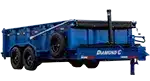
The Diamond C FMAX207 is a 15,500-lb GVWR Flatbed Max gooseneck offered in multiple deck lengths. Its current standard running gear includes two 7,000-lb Lippert axles. When configured with electric drum brakes on all four axle ends, the correct replacement magnet and expected electrical values should be determined from the Lippert axle identification label and brake assembly information. A tandem utility or equipment trailer with dual 3,500-lb axles commonly uses four 10 x 2-1/4-inch electric brakes, but its axle tags remain the final authority.
The Armature Plate: The Piece Most People Ignore
The magnet face rides directly against the armature surface inside the brake drum. On common trailer brake drums, this is a flat machined annular surface separate from the cylindrical surface contacted by the brake shoes. Both the magnet face and the drum’s armature surface must be flat, clean, and compatible for the brake to apply correctly.
A serviceable magnet normally develops an even wear pattern across its face. Inspect it with a straightedge in accordance with the axle manufacturer’s procedure. Uneven wear, pronounced grooves, exposed magnet-coil material, abnormal discoloration, broken lead wires, or a face that is no longer flat are reasons for replacement. The drum armature surface must also be inspected because installing a new magnet against a badly scored surface can quickly damage the replacement.
A magnet with a worn face may still pass a basic resistance or current test because the electrical coil remains intact. It can nevertheless produce poor braking if it cannot maintain proper contact with the armature surface or move the actuating lever correctly. That is why an electrical reading alone cannot establish that the complete brake assembly is healthy.
Inspect the brakes at least annually or every 12,000 miles unless the applicable axle or trailer manual calls for a shorter interval. Severe commercial service, frequent stop-and-go driving, mountain towing, water exposure, extended storage, or regular operation near the trailer’s ratings can justify more frequent inspection. Brake condition should also be checked whenever a hub is removed for bearing or seal service.
How Magnets Wear (and Why It Happens Fast)
Wear accelerates for a few specific reasons:
- Heavy service and excessive heat. Regular operation near the trailer’s legal ratings makes the entire braking system work harder, particularly in traffic or on long grades. Overloading the trailer, an axle, a tire, a wheel, a hitch, or the tow vehicle is unsafe and can overheat brakes rapidly. Use the trailer certification label, axle ratings, tire capacities, actual scale weights, and tow-vehicle ratings when determining a safe load.
- Grease or oil contamination. A failed grease seal or improper lubrication can put grease on the magnet face, drum, or shoe linings. Contaminated linings can cause weak, uneven, or grabbing brakes and generally require replacement rather than cleaning. The leak must be repaired before the brake is returned to service.
- Corrosion and rough armature surfaces. A trailer stored in a damp environment may develop rust on internal drum surfaces. Light surface oxidation may wear away during normal use, but heavy rust, pitting, or scaling can damage magnets and shoes and requires inspection before towing.
- Incorrect controller adjustment. Excessive gain can cause harsh application, wheel lockup, and unnecessary brake heat. Insufficient gain makes the tow vehicle do too much of the stopping. Set the controller using its manufacturer’s road-test procedure, then readjust for meaningful changes in trailer load or road conditions.
- Dragging brakes or poor adjustment. Shoes adjusted too tightly, a seized component, a damaged spring, or a malfunctioning self-adjuster can keep a brake dragging. Excessive clearance can delay shoe contact and reduce braking. Either condition can produce abnormal heat and wear.
Increasing controller output does increase the magnet’s attraction and braking action up to the system’s effective operating range. It should not be used to compensate for worn, contaminated, damaged, or badly adjusted brakes. If normal stopping requires unusually high gain, inspect the trailer rather than continuing to add controller output.
Diagnosing Amp Draw Problems
Begin with the trailer and controller manuals, the axle identification tags, and a confirmed wiring diagram. Secure the trailer, use properly rated lifting and support equipment if wheels must be raised, and never work beneath a trailer supported only by a jack. Then compare measured current with the specification for the installed brake assemblies.
Low Amp Draw (Reading Below Spec)
If a four-magnet tandem system expected to draw about 12 amps at full system voltage draws substantially less, something may be limiting current or one or more coils may be open. Work through this list:
- Verify the brake controller settings, controller capacity, tow-vehicle supply voltage, and the meaning of the controller’s display. Some controllers limit output while the vehicle is stationary unless the manual control is used.
- Inspect the tow vehicle’s 7-way socket and the trailer plug. Look for corrosion, looseness, bent contacts, heat damage, moisture, or poor pin tension at the electric-brake and ground terminals.
- Inspect the trailer’s brake-feed and ground wiring from the junction box to every axle end. Look for loose splices, undersized conductors, corroded connections, damaged insulation, broken wires near the backing plates, and grounds attached to painted, rusty, or contaminated metal.
- Measure system voltage under load. A no-load voltmeter reading can appear normal even when a high-resistance connection prevents adequate current flow. Compare voltage near the controller, at the trailer connector, and near the brake magnets while applying full test output.
- Isolate and test each magnet according to the manufacturer’s current or resistance specification. An open circuit indicates a broken coil or connection. A reading outside the specified range requires further isolation because harness resistance and parallel-connected magnets can distort readings taken at the trailer plug.
There is no single minimum-at-the-magnet voltage that applies to every controller and operating condition. The important issue is whether the brake circuit delivers the output commanded by the controller without excessive voltage drop. Compare both sides of the circuit, including the ground return, and use the manufacturer’s allowable values.
High Amp Draw (Reading Above Spec)
Current materially above the specified range can indicate a shorted magnet coil, damaged insulation, crossed wiring, or an unintended low-resistance path. A direct short may also cause a controller fault message, blown fuse, or protective shutdown instead of a stable high reading. Stop repeated testing if wiring becomes hot or the controller reports a fault.
Disconnect the trailer from the tow vehicle before performing resistance or continuity tests. Isolate branches and magnets systematically, repair damaged wiring with sealed connections of the correct gauge, and verify both current and braking action after the repair. Do not rely on the trailer coupler and hitch ball as the brake circuit’s primary ground; the trailer plug should provide a dedicated, properly sized ground path.
Correct Amp Draw, Poor Braking
This situation often causes confusion. The measured current may be close to the expected total while the trailer still brakes poorly. That result means the magnet coils are drawing current, but it does not prove that the mechanical brakes are adjusted, uncontaminated, or capable of producing full torque. Check:
- Magnet-face flatness, wear pattern, lead-wire condition, and free movement of the magnet and actuating lever
- Brake-shoe lining thickness and condition; Lippert service guidance calls for replacement when lining is below 1/16 inch, while contamination, cracking, separation, or heat damage can require earlier replacement
- Drum braking surface and armature surface for scoring, heat checking, glazing, pitting, excessive diameter, and out-of-round wear
- Manual adjusters, return springs, hold-down hardware, pivot points, and self-adjusting components where fitted
- Correct left-hand and right-hand brake assemblies and proper orientation of primary and secondary shoes
- Controller type, gain, boost setting, wiring capacity, and synchronization with the tow vehicle
Not every modern electric brake uses the same adjustment procedure. Some assemblies are manually adjusted, while forward self-adjusting brakes compensate during normal forward stopping after they are properly installed and initially set. Follow the instructions for the actual brake assembly rather than assuming every brake should be adjusted in the same way.
On manually adjusted brakes, the usual procedure is to tighten the star wheel until the drum has substantial drag and then back off the adjuster by the number of clicks specified by the manufacturer. The finished setting should produce the appropriate light, even drag without binding. Always repeat the procedure at every braked wheel and reinstall adjustment-hole plugs.
On trailers we see come through Spencer Trailers, improper adjustment is one of the most common correctable causes of weak or uneven electric-drum braking. Adjustment should be performed together with an inspection because repeatedly adjusting damaged, contaminated, or worn components does not make them serviceable.
When to Replace vs. Resurface
Replacement magnets are generally inexpensive compared with the consequences of weak brakes, but price varies by axle capacity, brand, brake size, and whether the magnet or complete backing-plate assembly is replaced. If a magnet face is uneven, deeply grooved, worn enough to expose the coil, physically damaged, or electrically outside specification, replace it with the correct part for that brake assembly.
Field grinding or sanding is not an approved substitute for replacement. A replacement magnet must be compatible with the brake size, actuating lever, spring, retaining hardware, and drum. Because the shoes, springs, adjuster, lever, and magnet wear together, replacing the complete brake assembly can sometimes be the safer and more economical repair, especially when several components are near their service limits.
Drums require careful measurement. A lightly oxidized service surface may be cleanable if it remains smooth and within specification. Scoring, heat damage, excessive runout, an out-of-round condition, or wear beyond the maximum inside diameter may require machining by a qualified brake shop or complete replacement. Machining is permitted only when enough material remains to stay within the drum manufacturer’s service limit.
The maximum allowable drum diameter is normally cast or stamped into the drum or published for its exact part number. Do not apply a measurement taken from another brand or another 12-inch drum to the one in front of you. The braking surface contacted by the shoes and the armature surface contacted by the magnet must both remain serviceable.
Current Diamond C premium trailers, including the FMAX line, use Lippert axles as standard. A current Diamond C FMAX207 uses two 7,000-lb Lippert axles, commonly paired with 12 x 2-inch electric drum brakes when ordered with that braking configuration. Confirm the axle serial number, hub-and-drum number, and brake label before ordering parts because production specifications and optional equipment can change.
A Quick Troubleshooting Sequence
Symptom: Brake circuit current is near specification, but the trailer pushes the tow vehicle on downhills.
Likely cause: Incorrect adjustment, contaminated or worn shoe linings, damaged drum surfaces, glazed or uneven magnets, overheated brakes, or controller setup that is not synchronized with the load.
First check: Allow overheated brakes to cool safely, verify controller setup, then inspect and adjust every braked wheel according to the manufacturer’s procedure.Symptom: Measured current is below specification and the brakes feel weak.
Likely cause: Inadequate controller output, corroded connector contacts, a poor ground, high-resistance wiring, a broken connection, or one or more open magnet coils.
First check: Confirm controller operation, inspect the 7-way connector, perform loaded voltage-drop tests, and isolate each magnet.Symptom: One wheel locks while the others barely engage.
Likely cause: Uneven adjustment, contamination at one brake, mismatched assemblies, a seized or damaged mechanism, poor wiring to the weaker brakes, or different drum and lining conditions from wheel to wheel.
First check: Compare temperature and braking action carefully, then inspect wiring, adjustment, shoes, magnets, hardware, and drums at all braked wheels.
A magnet coil short does not route extra controller current through the other parallel-connected magnets in a useful way. Depending on the controller, it may increase total current, trigger overload protection, blow a fuse, or shut down brake output. A single locking wheel is therefore not enough evidence to diagnose a shorted magnet without electrical and mechanical testing.
Buying a Used Trailer? Check the Magnets First
If you’re browsing our inventory or evaluating a used trailer elsewhere, the brake assemblies can reveal a great deal about prior service. With the trailer safely supported, remove each hub-and-drum assembly and inspect the magnet wear pattern, shoe linings, springs, adjusters, seals, bearings, wiring, and both working surfaces of the drum.
Deep grooves, exposed magnet coils, grease-soaked linings, loose hardware, heat discoloration, broken wires, or shoes worn to the service limit indicate that repair is needed before the trailer returns to the road. New magnets alone may not solve the problem if the armature surfaces are damaged, the drums exceed their service limits, or the brake shoes and hardware are also worn.
Also verify that the trailer has brakes appropriate for its actual ratings and intended operation. Indiana law requires a trailer or semitrailer with a gross weight of at least 3,000 pounds, when operated on a highway, to have brakes adequate to control, stop, and hold the vehicle. Those brakes must be controllable from the towing vehicle’s cab and must apply automatically if the trailer separates. Current Indiana law generally requires service brakes on all wheels of a new trailer sold in the state, subject to the statutory exceptions.
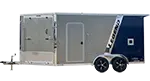
Commercial cargo trailers such as a Legend Explorer aluminum cargo trailer or a Wells Cargo FastTrac may accumulate substantial mileage depending on their use. Model name alone does not identify the installed brake size or magnet. Read the certification label and axle tags, confirm whether every required wheel is braked, and compare the components with the applicable manufacturer’s service information.
A well-maintained electric-brake system should show reasonably even wear from wheel to wheel, dry linings, serviceable drums, secure wiring, correct adjustment, and smooth response during a controlled road test. Uneven wear can point to a wiring, adjustment, loading, or component problem that affects the entire trailer even if only one wheel looks noticeably different.
Electric brakes are not complicated, but they require consistent inspection and correct adjustment. Test brake response before every trip in a safe area, verify the controller whenever you change tow vehicles or significantly change the load, and inspect the complete brake system at the interval specified by the axle manufacturer. Check the breakaway switch and battery as directed by their manufacturers as well; the breakaway system is an emergency device, not a parking brake or routine test control.
Never exceed the trailer GVWR, axle GAWRs, tire or wheel ratings, coupler or hitch rating, or the tow vehicle’s published limits. Properly functioning magnets cannot compensate for an overloaded combination, insufficient tow-vehicle capacity, overheated brakes on a long descent, or poor load distribution. Use a lower transmission gear on grades and follow the tow-vehicle manufacturer’s instructions rather than relying on the trailer brakes alone to control speed.
Have a brake issue you can’t diagnose from the controller? Reach out to us at Spencer Trailers and we’ll help you work through it. (812) 829-0226.


